ME ENGINE ELECTRONICS FULL GUIDE
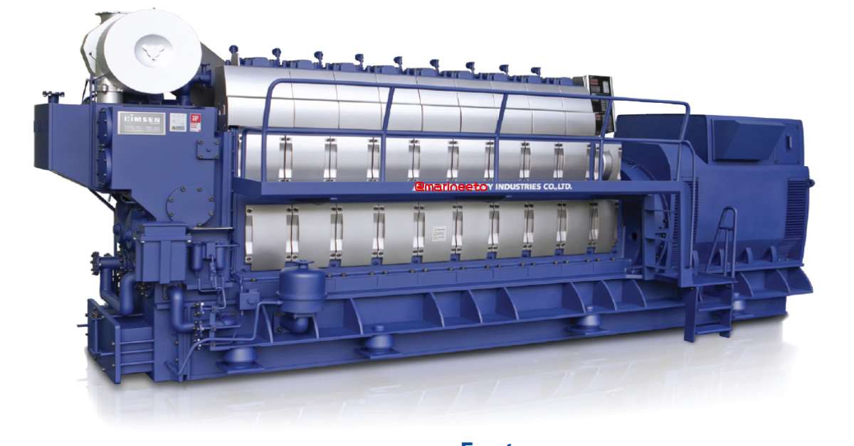
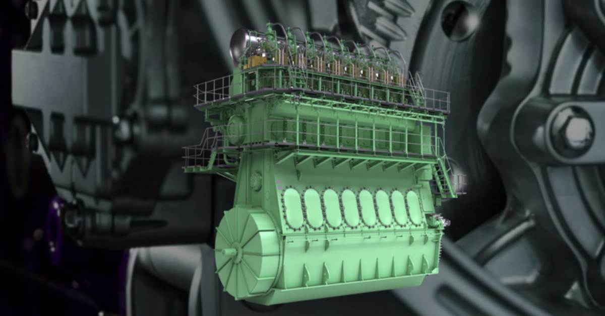
ME engine electronically controls fuel injection, cylinder lubrication, and the timing on elements such as the exhaust. In order to create an engine that corresponds to international emission regulations and achieves low fuel consumption for the protection of the global environment, the introduction of electronic control was inevitable due to the limitations of conventional machine control. This post describes ME engine electronics full guide.
There are two versions of ME engine,
- ME-C uses electronic control on both fuel injection (FIVA Fuel Injection Valve Activation) and the exhaust valve (ELVA Electronic Exhaust Valve Activation).
- ME-B uses electronic controller dedicated solely to fuel injection (ELFI Electronic Fuel Injection) and designed as a cost-effective version of the earlier ME-C engine
ENGINE COMPARISION
| CONTROLS | MC | ME-C | ME-B |
|---|---|---|---|
| Fuel Injection | Camshaft | Electronic (HCU) | Electronic (Dual HCU) |
| Exhaust Valve | Camshaft | Electronic (HCU) | Small Camshaft |
| Cylinder Oil Lubricator | Camshaft | Electronic (ALS) | Electronic (ALS) |
| Starting Air Distributor | Camshaft | Electronic (Solenoid) | Camshaft |
ENGINE CONTROL COMPONENTS
ME engines employs of various Electronic Components, Valves and Sensor for Engine Control,
- MOP (Main Operating Panel)
- ECS (Engine Control System)
- HPS (Hydraulic Power System)
- Tacho System
MOP (MAIN OPERATING PANEL)
MOP is HMI (Human Machine Interface) screen provides main information for engineer operating the engine. The actual installation consists of two touchscreen MOP-A and MOP-B. Using MOP engineers can give Engines commands, Adjust Parameter, and also see the status of ECS.
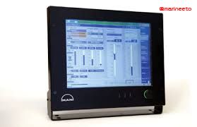
MOP also gives troubleshooting information, off scan alarm function(Cut-out), view network status and sensor data.
MOP function overview
- Displays ECS data- Human Interface
- Parameters Handling
- ECS alarm Handling
ECS (ENGINE CONTROL SYSTEM)
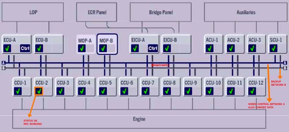
ECS consists of a list of controllers. The function and description of each function are given below.
- EICU
- CCU
- SCU
- ACU
EICU (ENGINE INTERFACE CONTROL UNIT)
EICU handles external systems and HPS (Hydraulic Power Supply). The main command is speed setpoint. In the EICU speed setpoint is processed by a series of protective algorithms.
If EICU fails the only possible way to control the engine is ESC (Engine Side Control) or BCU( Backup Control Unit) if provided.
ME engines have 2 different running mode i.e., Emission & Economy and also 3 different Governor mode i.e., RPM control, Torque control, and Index control.
Based on the algorithm of selected engine running mode, the injection profile is selected, timing parameters for fuel injection are calculated and EICU derives the pressure setpoint for hydraulic power supply.
EICU function overview
- ECR/Bridge Selection
- HPS Control Setpoint
- Cylinder Lube Feedrate
- General Alarm Relay
- Slow Down Request & Command Relay
- Engine Running Mode
CCU (CYLINDER CONTROL UNIT)
CCU handles ELFI (Electronic Fuel Injection) valve, Cylinder Lubrication i.e., ALS (Alpha Lubricabor System), and distributed governor. Similarly FIVA (Fuel Injection Valve Actuation), ELVA (Electronic Exhaust Valve Actuation) for ME-C engine. FIVA & ELFI are the same and have a similar function and these valves operate proportionally.
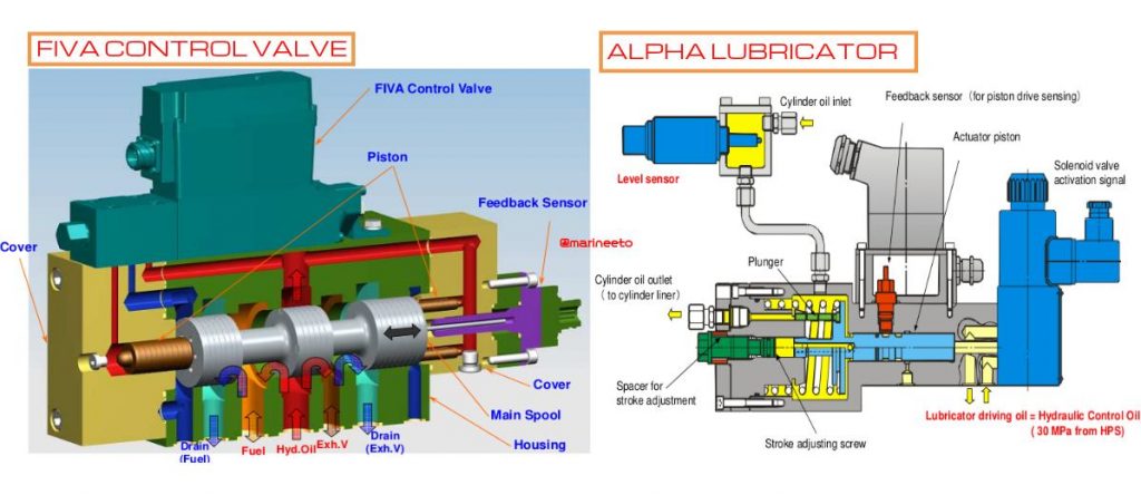
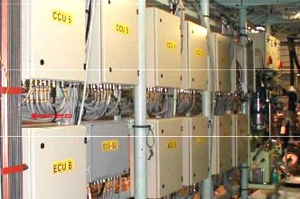
The position of these valves is transmitted by a feedback sensor. Each cylinder of the ME engine has a dedicated CCU unit. For Example, 6 cylinders will have 6 CCUs.
The CCU selects injection profile based on crank angle feedback from Tacho System and requested fuel injection profile, timing parameter, feed rate, and injection angle received from EICU via the control network.
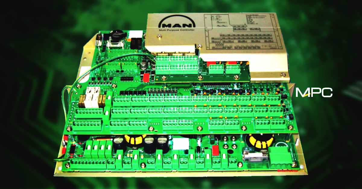
The cylinder lubricator is activated according to the cylinder oil feed rate received from EICU. The controller used in CCU & EICU is MPC. Lubricator is also provided with a solenoid valve(for injecting cylinder oil) & a spool position sensor and flow sensor.
CCU function overview
- HCU valve control & supervision
- Speed Governor
- Local/Remote Selection
- Shut Down Monitoring from Safety system
SCU (SCAVENGE AIR CONTROL UNIT)
This is Optional. SCU uses scavenge air Bypass or VT(Variable Turbine/Turbocharger) to control scavenge air pressure. SCU is connected to the ECS network. The estimated engine load and the measured scavenge air pressure from ECS. The SCU will set a setpoint for the Pscav controller based on Engine load.
Pscav controller will also receive a feedback signal from scavenge air receiver sensor and calculates setpoint to exhaust gas bypass or VT actuator. The controller used in SCU is MPC.
ACU (AUXILIARY CONTROL UNIT)
This is optional, Auxiliary control can be made using starter panel by yard manufacturer. The Auxiliary Control Units control the pumps of the hydraulic system unit and the auxiliary blowers. Separate Cabinet for ACU may be provided.
ESC (ENGINE SIDE CONTROL)
In case main operation fails from Bridge/ECR engine still be controlled from ESC which consist of LOP and ECU.
LOP (LOCAL OPERATING PANEL)
LOP is substitute for previous ESC (engine side control). Basic functions are available for controlling engine such as stopping, starting, ahead/astern movement, speed control.
ECU (ENGINE CONTROL UNIT)
LOP is connected to ECU which controls CCU. The Engine Control Units perform the engine control functions: engine speed, running modes and start sequence.
HPS (HYDRAULIC POWER SUPPLY)
The hydraulic power supply consists of two electrically driven hydraulic axial piston pump which is covered by a cylinder frame. These pumps can be started in Auto (ACU may be provided) or Manual mode. In auto mode, when you select engine standby automatically these pumps will start to achieve set pressure(max 300bar).
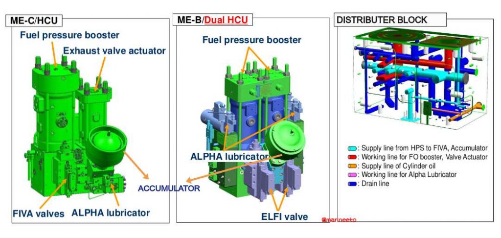
This pressurized oil is fed to the distribution block in which HCU (Hydraulic Cylinder Units), Exhaust Valve Actuator, ALS is mounted. HCU consists of a fuel oil booster, Exhaust valve actuator. When the ELFI/FIVA valve operates fuel pressure is boosted and fed to fuel injectors through a high-pressure pipe for atomization. For Example: If fuel booster pump inlet is 7-8 bar is boosted up to 200-300 bar pressure which is outlet pressure.
TACHO SYSTEM
Tacho System consists of two main component,
- Angle Encoder
- TSA (Tacho System Amplifier)
ANGLE ENCODER
Earlier design had 2 sets of sensors total 8 sensors mounted on turning wheel which was expensive and time-consuming.
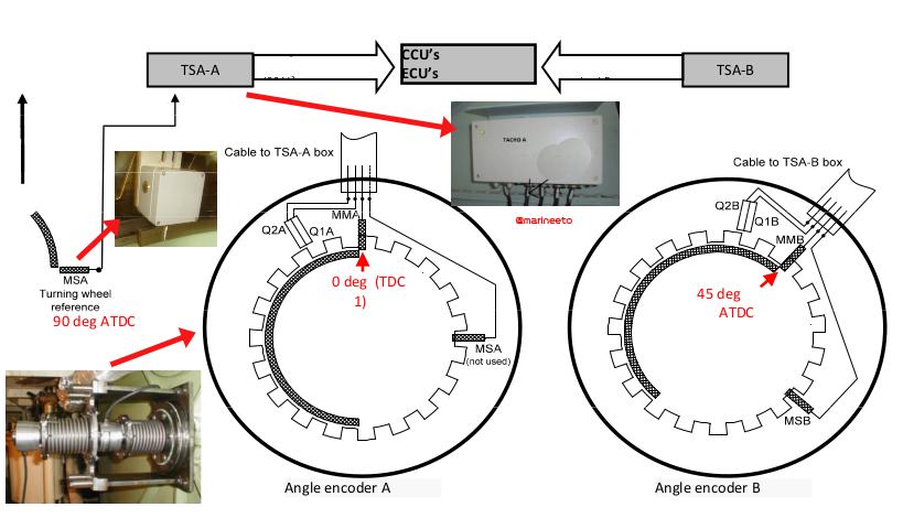
New Design consists of Angle Encoder which uses optical technology and easier to install since two rotary encoders are equipped onto the fore-end of the crankshaft (Each encoder gives an independent signal in consideration of the redundancy). Angle Encoder is basically a crank angle sensor. Each Angle encoder consists of 4 sensors namely, MM (Marker Master), MS (Marker Slave), Q1 (Quadrature Master), and Q2 (Quadrature Slave).
For Example, Angle Encoder A, MMA, MSA, Q1A, Q2A, and Angle Encoder B, MMB, MSB, Q1B, Q2B.
TSA (TACHO SYSTEM AMPLIFIER)
There are two sets of TachoSet, TSA-A, and TSA-B. TSA receives digital data from Angle encoder. The digital data is received MM (Marker Master), MS (Marker Slave), Q1 & Q2 (Quadrature). Refer table of sensor data received at various angles in degree at one revolution.
| SENSOR | 0-44 | 45-89 | 90-134 | 135-179 | 180-224 | 225-269 | 270-314 | 315-359 |
|---|---|---|---|---|---|---|---|---|
| MMA | TRUE | TRUE | TRUE | TRUE | FALSE | FALSE | FALSE | FALSE |
| MMB | FALSE | TRUE | TRUE | TRUE | TRUE | FALSE | FALSE | FALSE |
| MSA | FALSE | FALSE | TRUE | TRUE | TRUE | TRUE | FALSE | FALSE |
| MSB | FALSE | FALSE | FALSE | TRUE | TRUE | TRUE | TRUE | FALSE |
For TSA-A inputs from Angle Encoder-A are MMA, MSA (Angle Encoder A MSA output left floating and reference sensor is installed in the turning wheel is connected to TSA-A), Q1A & Q2A. Similarly for TSA-B but there is no reference sensor for TSA-B output of Angle Encoder B is fed.
Marker is used to track the position of the crankshaft, Similarly, Quadrature is used for speed and direction of shaft rotation(clockwise or anticlockwise). TSA data is fed to CCU.
PMI & CoCoS EDS
PMI continuously measures cylinder pressure to calculate mean pressure by the help of pressure sensor installed near indicator cock of all units, these sensors give 4-20mA signal to DAU(Data Acquisition Unit, which is MPC10 controller) that describes the combustion process they are,
- Pᵢ Indicated Mean Pressure
- Pₘₐₓ Maximum Pressure
- P꜀ₒₘₚ Compression Pressure
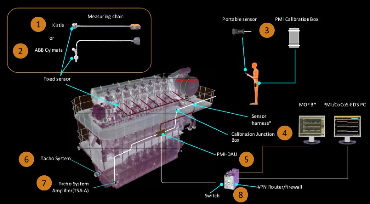
The data received at DAU is monitored by separate PMI PC in ECR known as CoCoS (Computer Controlled Survellience).
PMI & CoCoS EDS is not part of ECS but PMI data is available in MOP which is connected in network using Network switch.
MAINTENANCE & TROUBLESHOOTING
- Check AirGap and Keep sensing head of reference(MSA) sensor clean.
- Carry out PMI sensor calibration as per Ship PMS or Maker instruction.
- Take HCU event log Back-Up from MOP (this will help in future troubleshooting guide from the maker)
- Take PMI and CoCos-EDS Back-Up data. Restore it when necessary.
- Change Fuel data when changing fuel or using recent bunkered fuel.
- During routine maintenance also renew the Backup battery of MPC(Multi-Purpose Controller: Typical Battery life is 16000hrs/5 years).
ALSO READ: ME ENGINE MPC
Any suggestion write us mail@marineeto.we.bs
REFERENCES
- MAN energy solution marine.man-es.com
- MSR www.msr.co.jp/
- Hitachi Zosen www.hitachizosen.co.jp
LIKE POST? PLEASE SHARE







Very good explation
Thank You Iovi
Keep Supporting us
Like our social page to stay updated
How to restart shut down MOP A on ME engine
MOP TC SPEED FAILURE
MOP TC SPEED FAILURE
Thanks for sharing your knowledge
You’re welcome Kun Zaw Lin.
Keep supporting us.
It’s very useful. If possible pls post troubleshooting topics regarding ME engines
Thank You Sudhakara Reddy.
Your feedback matters a lot.
Will work on it in future post, keep supporting us.
Do share post to your colleagues
Thanks & regards
Admin
Man B&W 6G50ME-B.
We faced slowdown due to No.1 unit exhaust gas deviation..we changed both Fuel Valves..no change in deviation, then we replaced exhaust valve, the removed exhaust valve spindle found cracked.
After that for some days the deviation was low, but since yesterday it is increasing again.
Pmax for no. 1 and no.6 unit is high..Pi is also at higher side.
Note : All units decarb and Boosters done in Drydock in February 2024
Thank you very much for your detailed information. Can you please elaborate why ME-B is called dual HCU whether ME-C is single HCU?
Thank You, Nil.
Your comments matter a lot.
Refer to post, ME-B is a simplified version & cost-effective version of ME-C.
So Dual HCU is used in place of single HCU
Thanks & regards
Admin
Two HCUs are placed together in ME-B engine. That’s why dual.
Admin reply about Dual HCU is a lot of hogwash……
Good Day Neville Kootar,
your interactions matter a lot.
This post is about ME ENGINE ELECTRONICS, so HCU is a mechanical component so we don’t think much explanation is needed for HCU.
And please describe what made you feel hogwash?
If you feel hogwash write us at mail@marineeto.we.bs
Regards,
admin
What is high off load and low off load in ME-C engine MOP
Good day T.Elango,
your interaction matters alot.
For better explanation refer below link
http://marengine.com/ufiles/SL07-480.pdf
Regards,
admin
Is it ME-C dual-fuel engines?
In the gas version shut down is released when gas concentration is too high.
Please help me evaluate this scenario, what would be the possible remedy..?
Elect hydraulic start up pump 2 is on. Master control. And pump 1 on slave.
1) During engine start up. Pump 1(slave) is running continuously instead of pump 2 as the master.
2) Pump 1 cannot be selected as master anymore as it appears the button selector is inhibited even in Chief user.
Do you have an HPS pump starter panel?
Make sure the relay associated with the Master & Slave selector switch are working fine.
What is the setpoint pressure? Sometimes if the setpoint is not achieved both the pump may run.
If still, the problem exists contact maker.
Try it doing from GSP panel. There will be selector switch to change P1 or P2 or both
What happens if CCU fails?
Engine will slowdown
Thank you
What can be cause of noice level increas in CCU,
How to rectify?
check twisted pair cables connected to MPC or may be due to MPC earth fault. Use MPC earth fault finder device to check this.
How to repair ME-B ECS SYSTEM FAIL?
very helpful guide note
We do have encountered ME Exhaust Temperature Low Deviation on one cylinder – 50 degrees. We have replaced fuel injector & Overhauled Booster pump but still the same outcome? What seems to be the problem? We are planing to replace ELFI valve.
You can report this issue to maker they can guide you better.
Pl begin with a simple check on your fuel filters. Is your fuel pressure alright? If not clean the filters and retry. Is your engine on LSMGO and you just overhauled your fuel booster? Then the seals are still running in. Once you run on HFO, the fuel booster gets heated up and the seals run in, the exhaust deviation may vanish.
Replace the ELFI only after these checks.
Hello.
Where in CoCoS change fuel data(dens,visc etc)
Thanks in advance
COCOS connected to MOP via PMI router. RPM, fuel data,etc acquired from there.
thank you
admin
Good initiative.Thank you. Appreciate your efforts.
thank you keep supporting us
Very useful informative information
thank you gopi, keep supporting us
hello everyone, just like to ask in ME-B engine there is no ECU installed. just curious what is the alternative of the ECU in the engine control system.
many thanks.
Yes, in such case your CCU will perform functions of ECU.
Thanks a lot for your information about the M.E -B & M.E-C engine and it’s very helpful to me.
thank you keep supporting us
Wonderful article, highly appreciate.
thank you chief
Very informative.
when to use rpm control and torque control in MOP
If you are tuning, calibrating or manouvering better to use RPM mode.
When the weather is rough & you see RPM hunting, Fuel index hunting, change to Torque mode.
Interesting article, well explained.
Can you explain the reversing procedure for MAN B&W ME engines?
Thanks
what is the purpose of the accumulator in me engine
Anyone face problem with ME engine MOP A screen?Before many times it is switching off and then restarting automatically and this time it is not even switched off only brightness control knob is blinking red and green
Contact maker, may be hardware issue with MOP panel
We have a case of both MOP failed due to display error on a 3 year old vessel (ME-C8 engine) and unable to reset by restarting. If continue to sail with the defects to next port, what are kind of controls and ECS alarm monitoring functions are affected? Many thanks!
MOP runs program in windows xp on 32SSD inbuilt. If your os corrupted try to reboot using USB recovery stick attached on EC-MOP. If not available contact maker.
Nothing should be affected when you turn off & on. MOP is interface between ECS & Operator.
Thank You,
admin
Good day. We have lost communication with PMI-DAU 11. No attained MAC and IP adress. How to restart PMI-DAU?
Check the network connector & PMI router. Sometimes wires break in connector which leads to communication error
Explaination about MPC (multi purpose controller ) is missing .
check our next link or search mpc in search detailed information is given.
thank you,
admin
Thank You so much for your knowledge sharing.But i am a little confused in Tacho system.Why TSA-A need reference sensor(MSA on flywheel) ? TSA-B use MMB,MSB,Q1B,Q2B unlike TSA-A. if TSA-A failure, TSA-B will take action without reference sensor from flywheel.
please can you explain for me?
Thank You.
The reference sensor from Tacho encoder A Master marker sensor. was installed in the flywheel this sensor was intentionally separated from Tacho A so that if in case tacho A will be accidentally misaligned or moved there is still one reference sensor installed which is secured in the flywheel. in this case ECS can still continously receive electronic signals from tacho encoder.
Very useful and informative
ME ENGINE crash astern procedure
please explain the experience or maker instructions
I just need to know about.Emergency manuring,How it done with LOP.
Thank you
Please what is the reason for EICU cylinder deviation alarm .
Two HCUs are placed together in ME-B engine. That’s why dual.
Is fuel injection controlled by crank angles or, milliseconds in ME engines?
sir i appreciate for the detail explanation of the me engine ecs and am facing a problem on my ecs with an alarm code that says gamma40communication fault to panel 1
and it says cold start running but then it says network time out and block the start of the engine. we are currently in china which has very cold weather so do you have any suggestion to what might be the problem. thanks
Pl begin with a simple check on your fuel filters. Is your fuel pressure alright? If not clean the filters and retry. Is your engine on LSMGO and you just overhauled your fuel booster? Then the seals are still running in. Once you run on HFO, the fuel booster gets heated up and the seals run in, the exhaust deviation may vanish.
Replace the ELFI only after these checks.
Hello sir I am facing an issue with HPS pump in ME B engine .When we put control at standby one pump which is at master mode that one is started so today that pump is started and after 30 min it is automatically stopped without any alarm on MOP panel and start blocked is activated What is the problem sir?
Check pump abnormal alarm is connected to MPC or not.
If facing same issue again, report to maker.
Dear Admin ! Good day !
I would like to ask you about one question . Sorry , can’t find . how to read graphs on SPAF file , which we took for troubleshooting of HCU Events , for me more important
numeric value on axis . Will be glad to hear some shore comments on my request . With BRGDS Cheng Igor
You need program to see graph of extracted HCU events from MOP. Program name is “LDEPlot.exe”
Thank you
Hello how to check Engine Timing in ME-C Engine
Thank you in advance.
how to trouble shoot ME-B ECS SYSTEM FAILURE
Hello
We r facing issue with PMI signal not valid showing on PMI PC.
Also signal not available at MOP PC. Pls advice
Thinking you in advance
Hello
We r facing issue with PMI signal not valid showing on PMI PC.
Also signal not available at MOP PC. Pls advice
Thinking you in advance
Check the connector which connects PMI router & DAU (MPC 10).
Most of the cases the wires inside connector in PMI DAU (MPC 10) are not intact or damaged.
Very nice
In a new vessel m.e HYUNDAI MAN B&W 6S60ME-10.5HPSCR TIER II &TIERIII 11610kw.
On d.s low revolution the pi very very low and turbo have charging.??
Thanks you. Can i simulate MOP? Which chanel?
Probably check first the exhaust gas thermocouple to the specified cylinder maybe faulty