PROGRAMMABLE LOGIC CONTROLLERS COMPLETE GUIDE
PLC-Programmable Logic Controllers is a digital electronic device that contains a programmable (changeable) memory in which a sequence of instructions is stored. Those instructions enable the PLC to perform various useful control functions like relay logic, counting, timing, sequencing, and arithmetic computation.
These functions usually are used to monitor and control individual machines or complex processes via inputs and outputs (I/Os). I/O modules connected to the PLC provide analog or digital electronic interfaces to the external world. The PLC reads inputs, processes them through a program, and generates outputs.
HOW DOES PLC WORKS?
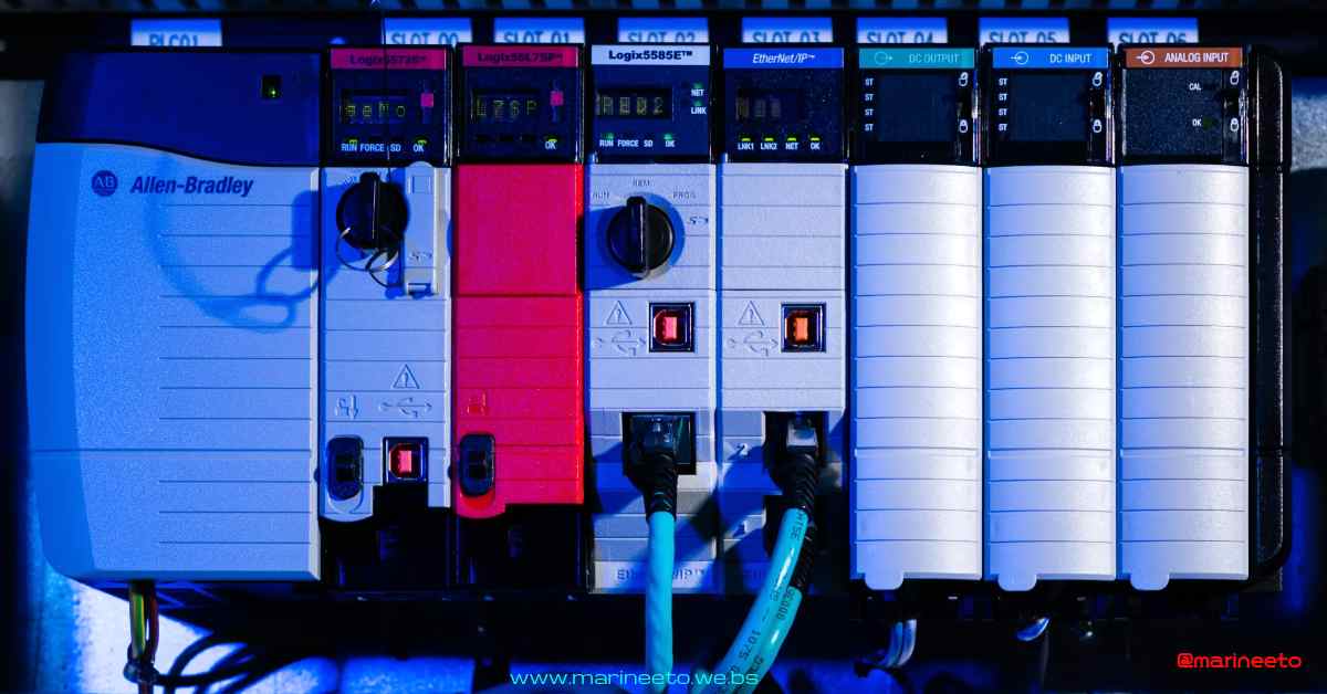
PLC(Programmable Logic Controllers) receives inputs from various devices and controls output devices based on instructions saved in the memory. PLC consist of the following components,
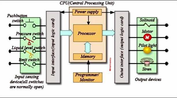
POWER SUPPLY & RACK
- The rack is the component that holds everything together. Depending on the needs of the control system it can be ordered in different sizes to hold more modules. Like a human spine, the rack has a backplane at the rear which allows the cards to communicate with the CPU. The power supply plugs into the rack as well and supplies a regulated DC power to other modules that plug into the rack. The most popular power supplies work with 120 VAC or 24 VDC source.
- The control of DC current flow is termed as sourcing & sinking.

CPU (Central Processing Unit)
- The brain of the whole PLC is the CPU module. The CPU consists of a microprocessor, memory chip and other integrated circuits to control logic, monitoring and communications. The CPU has different operating modes. In programming mode it accepts the downloaded logic from a PC. The CPU is then placed in run mode so that it can execute the program and operate the process. Since a PLC is a dedicated controller it will only process this one program over and over again. One cycle through the program is called a scan time and involves reading the inputs from the other modules, executing the logic based on these inputs and then updated the outputs accordingly. The scan time happens very quickly (in the range of 1/1000th of a second). The memory in the CPU stores the program while also holding the status of the I/O and providing a means to store values.
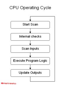
The Modes of CPU unit can be changed by turning key provided . Some PLC have DIP switch or LCD display to change mode. The modes used in PLC are,
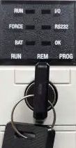
- RUN: The processor scans/executes the ladder program, monitors input devices, energizes output devices.
- PROG: This position places the processor in the Program mode. The processor does not scan/execute the ladder program, and the controller outputs are de-energized. You can perform online/offline(SD card) program editing.
- REM: This position sets the processor in remote test mode. You can perform online editing by Network or Serial data cable.
I/O (Input/Output Section)
- The I/O system provides the physical connection between the equipment and the PLC. There are many different kinds of I/O cards which serve to condition the type of input or output so the CPU can use it for its logic. Its simply a matter of determining what inputs and outputs are needed, filling the rack with the appropriate cards, and then addressing them correctly in the CPUs program.
I/O cards are sometime referred to as IO Module/Card & similarly input/ouput terminals are referred to as channels. These modules are categorized as,
- DI (Digital Input) module: Most commonly used DI inputs are Push Buttons, Selector Switch, Limit Switches, Pressure Switches, Temperature Switches, etc are connected to DI cards. DI card internal circuit consists of Photocoupler inputs. Typical digital input voltages are 12-24V DC or 120V AC.
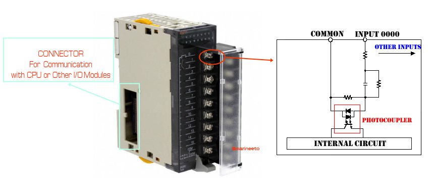
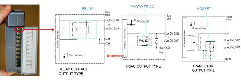
- DO (Digital Output) module: Output of DO card is connected to Relays, Indication Lights, Motor Starter, etc. DO card internal circuit may consist of a relay contact output or TRIAC output or Transistor output. Typical digital input voltages are 12-24V DC or 120V AC.
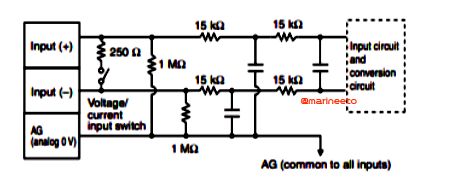
- AI (Analog Input) module: Typical analog signals come from temperature, pressure, position, and motor speed. Analog input modules convert analog signals to digital words (Basically internal circuits are made up of comparator or wheatstone bridge). Analog input signals are current or voltage. Typical analog inputs are -10 to +10V DC, 0-5V DC, 4-20mA.
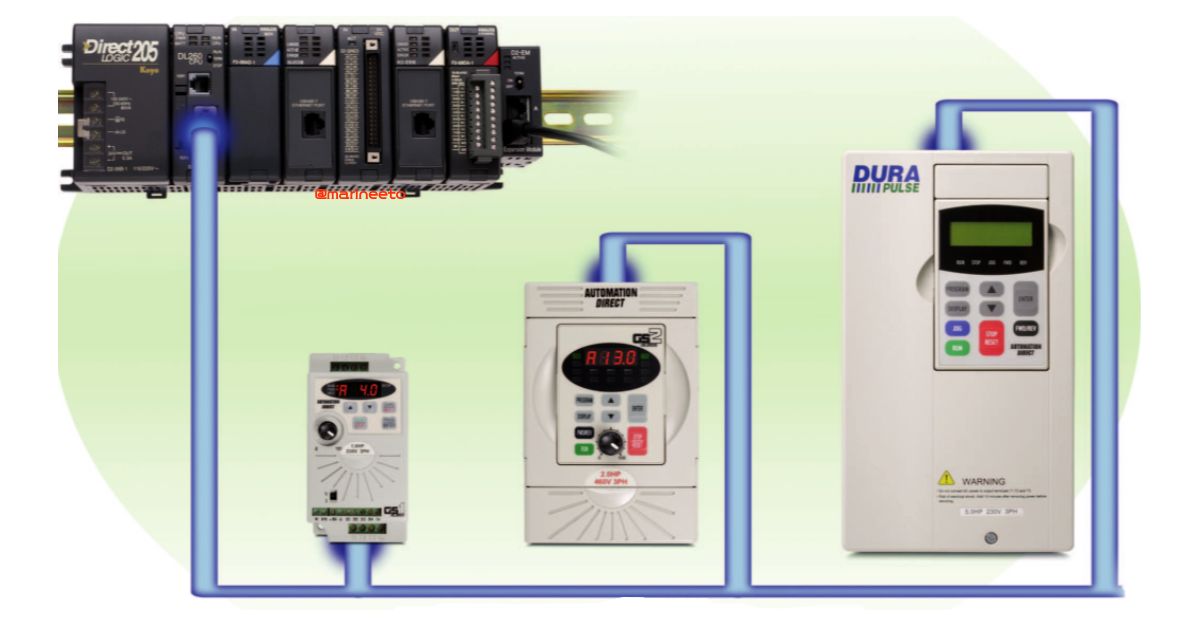
- AO (Analog Output) module: Typical analog signals are required by Proportional Valves, VFD, Servo Motors, Meters. Analog Output modules convert Digital bits to analog signal. Analog Output signals are current or voltage. Typical analog outputs are -10 to +10V DC, 0-5V DC, 4-20mA.

Also DX/DIO (Digital Input or Output) & AX/AIO (Analog Input or Output) modules are available.
Modern Programmable Logic Controllers come with an SD card slot, For Example: Allen Bradley RsLogix 5000 series, ABB AC500-XC series, etc. The Backup program is stored in the SD card. In case any modification in the program can be done by writing new program files to the SD card which can be loaded to PLC memory while booting. So the Lost program can be restored easily, Also can make a copy of current program by inserting a new SD card (only some PLC have this option).
WATCH VIDEO: LOAD PROGRAM FROM SD CARD TO PLC
Programs of PLC is written in specified languages, they are known as Ladder Logic. Ladder logic does not require any programming skills like C, JAVA, etc., any person with basic electrical knowledge can easily understand because its same as relay logic and easy to visualize so it is widely used for programming PLCs.
Another way to program PLC which includes complex algorithms is MATLAB-Simulink. Simulink is a MATLAB-based graphical programming environment for modeling, simulating, and analyzing multidomain dynamical systems.
LEARN PLC visit https://www.udemy.com
MAINTENANCE
- Air Filter & Fan Condition Checks: It is necessary to check the air filter and fan of the cabinet in which PLC is installed. The maker recommends maintaining the temperature of PLC within 60°C. Also while doing control panel routines restart PLC which helps to reset API, freezed programs & communication.
- Battery Replacement: The Battery is changed every 5th year to prevent failures. Some PLC lits up RED BATT LED when the life of the battery has deteriorated.
Switch off the Power supply before replacing (Most of the cases Battery is changed without switching off Power). Try to replace the battery within 3 minutes (some PLC need battery to be replaced within 20 seconds).
TROUBLESHOOTING
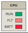
PLC is working normal or not is indicated by LED provided in CPU module or LCD display. When PLC CPU running normal RUN LED lits, If any fatal/non-fatal fault or an error occurs FLT LED lits & when the battery is low BATT LED lits.
- If PLC PWR LED not lit up or no power?
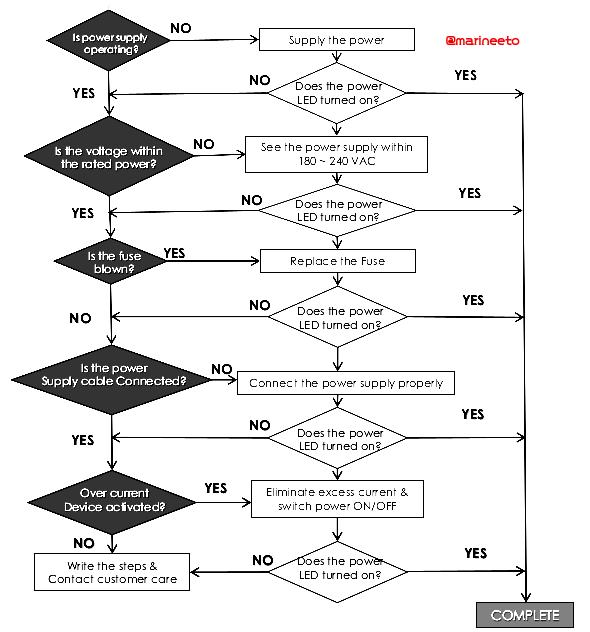
- If ERROR LED lit or flashing, if fatal eror then replace PLC else follow troubleshooting flowchart.
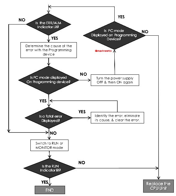
- If BATT LED lits up, replace battery.
REFERENCES
- SOLISPLC https://www.solisplc.com/
- NFI https://nfiautomation.org/
- OMRON PLC http://www.ia.omron.com
LIKE POST? PLEASE SHARE






Thanks for sharing such wonderful content, greetings from tsca.com.ph
very informative content. thank you