Ex PROTECTION SAFETY CHECKS ONBOARD TANKER SHIP
The tanker ship is considered more hazardous because it carries flammable, toxic, and reactive cargo. Flammable cargo is one of the deadliest properties to which proper concern and necessary safety precaution must be taken because it can lead to fire hazards causing major accidents.
However, the Tanker ship is provided with an Inert Gas System or N2 Generator thus reducing fire risk in the cargo tank. Also, the risks presented by static electricity discharges occur where a flammable atmosphere is likely to be present. The main precaution for tankers against electrostatic risks is to conduct operations with the cargo tanks protected by an inert gas.
The flammable atmosphere is known as Hazardous zones which are further classified as below,
- ZONE 0 The flammable mixture is continuously present or present for long periods. Zone 0 is Interior spaces of cargo tanks, pipes, pumps, etc.
- ZONE 1 The flammable mixture is not continuously present, but will be present during normal operations. Zone 1 is Enclosed or Semi Enclosed spaces, Battery rooms, etc.
- ZONE 2 The flammable mixture would not normally be present, but if it is, it would be present for a short period only. Zone 2 is open spaces on the deck.
Electronics & Instrumentation devices in these zones must be approved type and must be provided with a safety barrier, isolating safe and hazardous areas in the ship so that it will not provide sufficient energy to ignite vapours under fault conditions. Safety barriers are called intrinsic safety barriers (Ex-i) which are classified as given below
- Zener Barrier employs Zener diodes & Resistors to allow safe voltages and current levels for field devices. This means limiting circuit conditions to less than 30V and 50mA. Ex: Level Switch, Temperature Detector, Fire Detector, Ullage devices, etc.
- Active Barrier employs transformer, relays, isolator to provide isolation between safe and hazardous zone. The active barrier can drive a higher power load as compared to a Zener barrier. Ex: Solenoid valves, Transmitter, etc.
Ex-i further classified as,
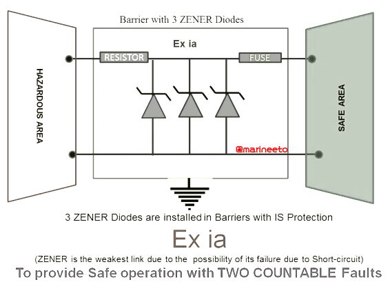
- Ex-i(a) is designed to be safe with 2 independent faults and can be used in Zone 0.
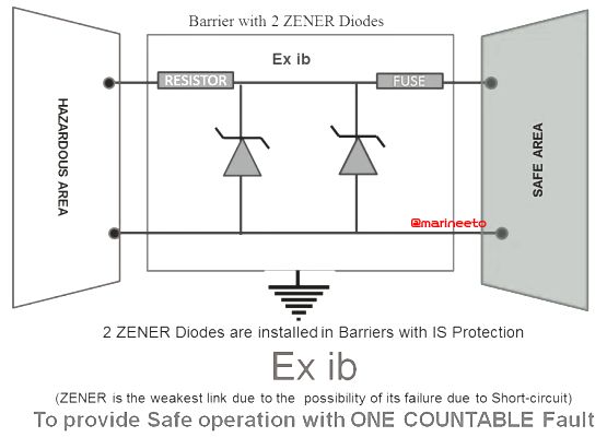
- Ex-i(b) has a lower level of integrity and cannot be used for Zone 0, the same will usually contain fewer Zener diodes as a part of circuit design and suitable for use in Zones 1 or 2.
LIST OF Ex SAFE EQUIPMENT CHECKS ETO MUST KNOW
Intrinsically safe devices must be checked to ensure the condition of the equipment and reduce risk factors in the worst scenario. Here is a list of safety checks that have to be carried out in Intrinsic safe equipment.
CARGO HOSES CONTINUITY TEST
This test ensures that the static electrical charge, which builds up in the cargo hoses during cargo operation, has a path to ground. If grounding is not proper it can lead to an explosion causing extensive damage or life-threatening injuries.
Electrically continuous hoses should not have a resistance higher than 0.75 ohms/metre measured between nipples (end flange to end flange) as shown in the below figure. This test is performed by using calibrated Multimeter (Digital Preferred) for accuracy. These readings are logged and kept for reference & documentation for during coastguard or vetting inspection.
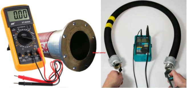
A similar test is also carried out for tank cleaning hoses and portable Framo hoses(if applicable).
Ex-d PROOF LIGHTS
Flameproof lights installed in zone 1, i.e, Cargo Locker, Paint Store, Pump Room, Battery Room, Deck Locker, etc. These lights have the property of containing an explosion within the lighting enclosure so that the ignition source does not come in contact with a Hazardous atmosphere.
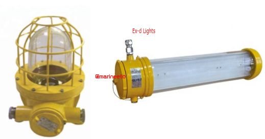
During routine checks its good to check all lighting enclosure conditions like water or dust ingress, Condition of cable gland & Junction boxes, Fused Bulbs, Globe & Guard. While replacing bulb also check the condition of the gasket.
ZENER BARRIER CHECKS
A Zener barrier is associated with equipment that is installed in a safe area. It is designed to limit the amount of energy that could appear in an electrical circuit passes through the hazardous area despite the connection before the barrier. A barrier consists of:
- RESISTOR to limit current
- ZENER diode to limit voltage
- FUSE to protect components
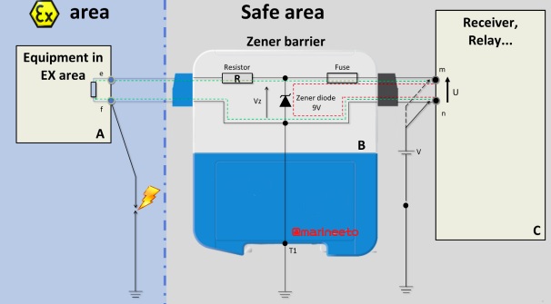
Check Zener Barrier is in operation especially for level switches which is remain normally open (NO) contacts all time, in case of short circuit fuse might get blown off, so regular check is required.
BONDING CONDUCTOR CHECKS
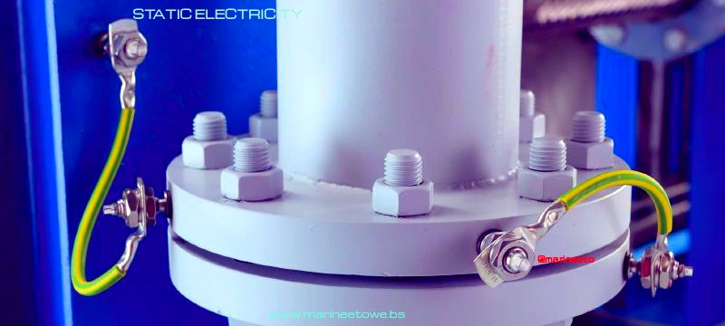
Bonding Conductors provides pathway to ground static charge. Bonding Conductor are placed between connection of two pipe flanges, Lighting Fixtures, Valves, etc.
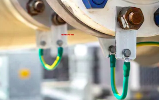
The Ohmic value of Bonding conductors must be less than 1 Ohms for proper grounding if it exceeds then these can be reason rusted or inappropriate contact, Breakage in Bonding link so replace it when ohmic value exceeds 1 Ohms else it may lead to danger. Also, it can be a high-risk remark during the inspection.
UTI DETECTOR CONTINUITY CHECKS
UTI (Ullage Temperature Interface Detector) periodic checks must be carried out. This is a frequently used instrument during loading and discharging operations. The test includes an open circuit and a grounding test.
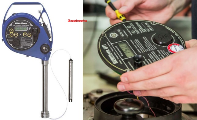
OPEN CIRCUIT TEST (CONTINUITY TEST)
The size of tape normally comes about 15-35 metres depending upon cargo tank size and sensor probe is connected at the tip of tape (sensor probe consist of Pt100 and conductivity sensor). So it is more likely that bending of tape can cause discontinuity.
For open-circuit test, Disconnect the tape at the sensing probe side, Measure the resistance of each conductor of the tape i.e., between red and red, white and white, etc. The resistance should be less than 15 Ohms. If not, the tape might be broken.
GROUNDING TEST
Remove the battery, Measure the resistance between the ground (-) terminal of the electronic circuit and the tube of the sensing probe the resistance should be less than 10 Ohms. If it is higher, the steel tape might be broken or the connection between the sensing probe circuit and the sensing probe tube might be interrupted.
PROTECTION STANDARDS
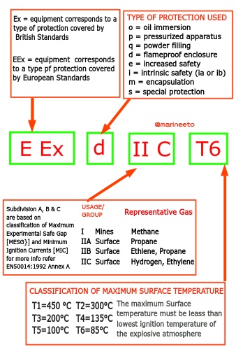
Ex equipment corresponds to the type of protection covered by British standards and EEx corresponds to European standards. While considering the protection against electrical arcs and sparks igniting a flammable atmosphere, consideration needs to be given to the surface temperature of the equipment. (Most of the electrical apparatus dissipates some heat) Flammable material are categorized according to ignition temperature.
Again rather than work with an infinite range, six temperature classes are defined as follows which do not ignite below this temperature range, T1=450 °C, T2=300°C, T3=200°C, T4=135°C, T5=100°C, T6=85°C.
Refer Explanation of Marking of Ex-Equipment below
Use approved type devices in Hazardous zone starting from Ex-i torches to Ex-i camera.
Missed out something? Please mail us at mail@marineeto.we.bs
REFERENCES
- ELAFLEX https://elaflex.de/
- SENSORLAND www.sensorland.com
- EXPELTEC https://expeltec.com
LIKE POST? PLEASE SHARE









superb, useful keep rocking
Thank You Damodaram.
Keep Supporting us.
Thank you for this very informative and well explain blogs