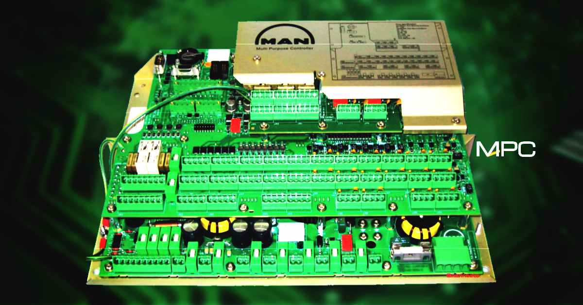
ME ENGINE MPC (MULTI-PURPOSE CONTROLLER)
MPC is one of the important electronic controllers used in ME engine. It receives/transmit inputs and outputs from various sensor and actuators, provides information about engine parameters to MOP.
MPC OVERVIEW
The Main processor used in MPC is Motorola 68332 which is 32bit CPU & is widely used in the automation industry. It also comes with a co-processor for synchronizing crankshaft rotation and speed data.
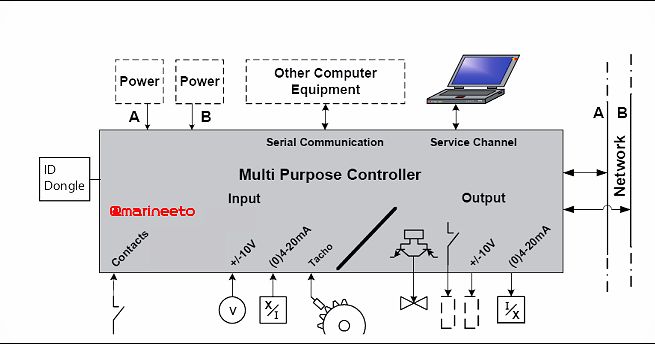
MPC has no user interface devices like Keyboard, Mouse, Monitor,etc. has got wide range of I/O(input/output) ports for interacting with sensor and actuators.
MPC uses FPGA(Field Programmable Gate Array) technology. The software is stored in non-volatile Flash PROM Memory, this allows application software to send program through wired bus network.
All component of ECS has designated MPC, Example: Each Cylinders CCU will have separate MPC i.e., for 6 Cylinder engine, 6 CCU & each CCU with one MPC which totals 6 MPCs Similarly for EICU, SCU.
MPC SPECIFICATION
MPC is powered by a 24V DC power supply also it is equipped with backup battery (BR2032-Lithium Poly Carbon Monofluoride Battery Coin 3V 190mAh).
The backup battery provides backup power to clock-watch when 24V DC is turned off.
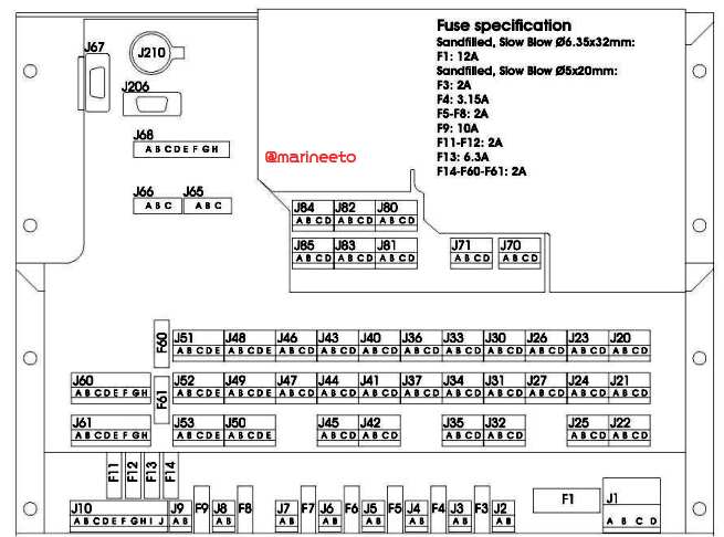
MPC has various terminals(J-plug) and fuses their functions are mentioned below.
| J-PLUG NO | FUSE NO | FUNCTION |
|---|---|---|
| 1 | F-1 | Power Supply |
| 2 | F-11 | Power Failure |
| 3-9 | F-3 to F-9 | Power out 24V |
| 10 | Connecting Terminals(loop etc) | |
| 20-37 | F-12 | Analog input |
| 40-47 | F-13 | Fast Digital Input |
| 48-53 | F-13 | Fast Digital Input/Output |
| 60-61 | F-13 | Digital Output |
| 65-66 | Network Connection | |
| 67 | Service Terminal | |
| 70-71 | F-14 | Analog Output |
| 80-85 | Digital Output | |
| 206 | Dongle Key Connect | |
| 210 | Battery |
MPC is provided with Dongle-Key, When new is mounted the dongle tells MPC to which group & which cabinet it is mounted Example: EICU, CCU-1, or SCU. Keep your Dongle-Key safe while replacing MPC same must be inserted to the new MPC else new Dongle-Key must be programmed.
MPC is also equipped with a tri-color LED. LED displays 3 colors namely Green, Yellow, and Red. When MPC runs normally GREEN light is lits up. Also LED helps in troubleshooting MPC. LED lits YELLOW when MPC is in Test or configuration mode & RED when there is ERROR in MPC.
A RESET button is provided to restart MPC in case any ERROR is triggered.
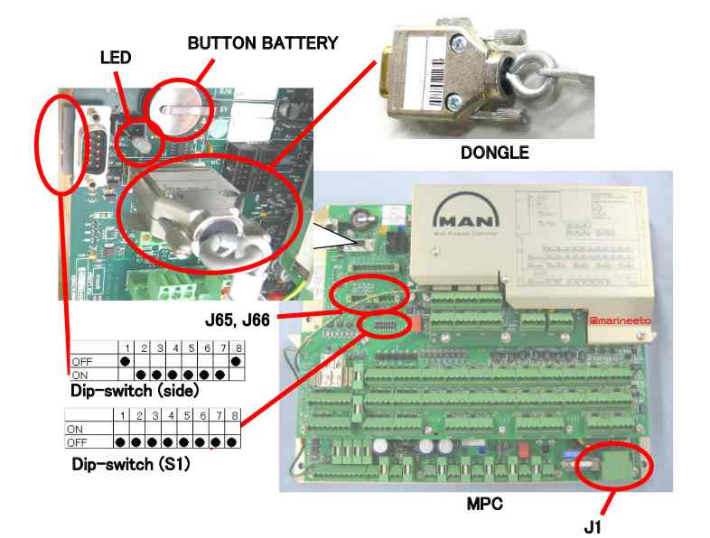
DIP SWITCHES: two DIP switches are provided, 1 Multicolour Dip switch at side & other DIP switch S1 in front.


- Multicolor DIP switch 1& 8 is OFF since it is for connection test and normal service. Other switches are used for enabling/disabling Power, Watchdog Timer, etc (Refer Manual).
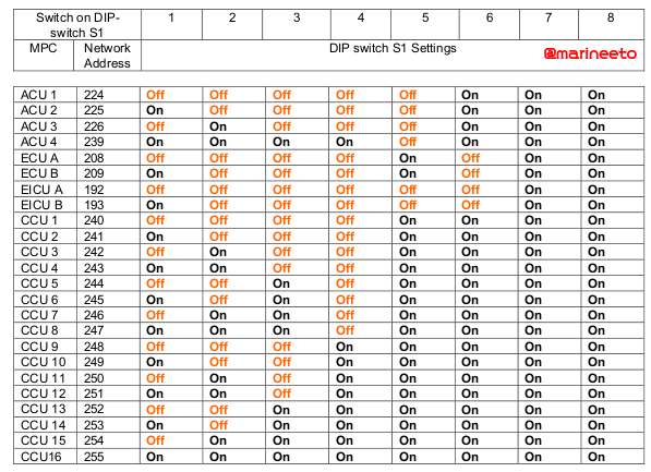
- DIP Switch S1 all switches in OFF position normally. It is used for programming new ID-KEY DONGLE.
Noise & Insulation level of MPC is monitored. The alarm is activated when insulation or noise is below the desired level. IRM(insulation Resistance Monitor) module is mounted on MPC to monitor the electric insulation level.
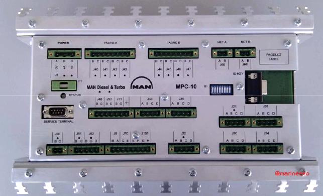
MPC-10 is a simplified & cheaper version of MPC which lighter & smaller compared to other MPC. It has 20 external connectors whereas MPC has 55 external connectors this is mainly used in PMI-DAU which supports up to 20 cylinders.
TROUBLESHOOTING
The MPC LED shows indications by either emitting constant light or by flashing. The LED indications are identified by the colour that the MPC LED emits.
Flashing LED indication consists of two pulse trains separated in time by 1-second pauses. All pulses are set against a yellow background. The first pulse train will change between a yellow background and a red foreground, and the second will use green as the foreground.

To identify the LED colour code note the number of red and green pulses. The first digit is the number of red pulses and the second digit is the number of green pulses. In the illustration above, the colour code is (2, 3).
1.CONSTANT
| COLOUR | SHORT NAME | DESCRIPTION |
|---|---|---|
| RED | ERROR | Early initialization or Fatal error |
| YELLOW | INIT | Initialization, No parameters available |
| GREEN | NORMAL | Running |
2. FLASHING
| COLOUR (RED,GREEN) | SHORT NAME | SHORT DESCRIPTION |
|---|---|---|
| (1,1) | CTRL_PRG | Onboard control programming in progress |
| (2,1) | APPLOAD_SCAN | Application download in progress-scanning for server |
| (2,2) | APPLOAD_DOWNLOAD | Application download in progress-downloading program |
| (2,3) | APPLOAD_DIP | Application download completed-reset yellow DIP switch set to ON |
| (3,1) | BOOTLOAD_SCAN | Boot loader download in progress-scanning for server |
| (3,2) | BOOTLOAD_DOWNLOAD | Boot loader download in progress-downloading program |
| (4,1) | DONGLE_VERIFY | Checking node ID dongle |
| (4,2) | DONGLE_ERROR | Dongle error-missing, broken or not programmed |
| (4,3) | DONGLE_DIP | Node ID DIP switch not correctly reset-reset it to 0x00 |
| (4,4) | DONGLE_FORMAT | Waiting for confirmation to reformat the records in the Dongle with Start up and Persistent Data Area information. |
| (4,5) | DONGLE_DIP_CONFLICT | ID key not connected, no usable address supplied from DIP or Service Terminal. |
| (5,1) | DIP_ILLEGAL_RANGE | he selected address is outside the defined range 0xC0-0xFF (192-255). |
If you are using the new DONGLE KEY, you can program it by using DIP switch S1 in MPC. Refer to the table for the programming guide. Also, check LED status while programming.
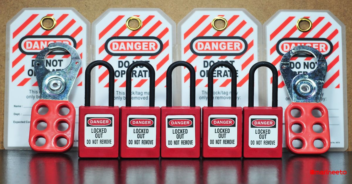
CAUTION: Static Electricity may harm MPC. While doing maintenance or changing battery level potential between hand and frame by touching a non-coated metal enclosure.
TIP: carry out maintenance on MPC when the engine is at stopped condition in port or anchor.
REFERENCE
- MSR www.msr.co.jp/
- MAN PrimeServ https://primeserv.man-es
Any suggesstion please write us mail@marineeto.we.bs
LIKE POST? PLEASE SHARE









Sir,if we change the Battery of MPC do we need to disconnect the power source J1?thank you
Thank You, Querubin Yngojo Jr.
Your comments matter a lot.
It can be done in two ways,
First, with power touch metal shield to balance potential, after removing old battery LED will lit up red & you get alarm, once you insert new battery the MPC will restart LED will blink orange continuously after few seconds LED will lit up green back to normal, Later you can reset active alarm in MOP.
Second way turn Multi colour Red DIP switch on side to OFF & insert new battery.
Regards,
Admin
Good day sir, we are now having troubles with electrical noise. Could you guide me on how to take ohmmeter readings from CCU to junction box and junction to FAVI/ELFI and other components? I am not an electrical engineer and we don’t have one onboard and my knowledge in electrical engineering are just basics. I hope you could help me with this one, Thank you!
Good day
as per maker notes loss of insulation give rise to electrical noise.
taking ohmmeter reading one by one is a hectic process as per maker troubleshooting guide suggests using heat-shrinkable tubes which provides an extra layer of insulation.
I recommend, visually inspect especially the junction boxes which are installed near to the hot surface. It might be because of damaged wires.
How to check? refer troubleshooting guide: https://yadi.sk/i/uIWOeu4qBxdR1A
thank you
thank you
Sir, can we change the battery on MPC when Main Engine running,and if YES how to do that…
Thanks
Good Day Zoran,
its not recommended to change battery while running.
when you remove you get alarm in MOP panel.
It may interrupt ME engine operation.
Recommended to do battery change, while vessel in port or anchor.
Regards,
admin
Hello Sir,
So,is not necessary to change battery immediately when appears alarm”Battery Low”,it can be done and later…I mean alarm”Low Battery” is not critical alarm, correct?
Battery serve as backup for settings.
If you cannot do while sailing, you can cut-out alarm & can do it later in port/anchor. carry out planned maintenance renew battery every 5 years to avoid this.
Regards,
admin
Do I need to disconnect power before removing battery? Or just simply remove the old one and insert new?
Hi. I have pressure switch (h.p. fuel pipe leakage) alarm. Is W 4112 to CCU 10 Connection j33 .
when I try to check it there is no reaction. is it possible that we do not have this function?
Are you sure it is a pressure switch normally it is a float switch.
When oil leaks the float lifts up activating alarm.
In my last ship, it was not part of ME ECS, It was part of E/R Alarm monitoring system.
Are you sure it is part of ME ECS?
Hi. Good day to all.
I have received an alarm on MPC – CCU5_SBAT. My question is – is it MPC or CCU5 and Can I just replace the battery by removing old and inserting new or I need to do something else for example disconnect power cable from MPC or CCU5.
Thanks in advance for small guidance.
Marek
You can just be quick,
Make sure you touch metal part before changing just to avoid risk of static charges.
Please advice,, backup battery replace procedure,, for CCU:
Good day!
Thank you for your helpful information.
Regarding for the case of changing used MPC with new MPC
I have checked manual but there is some unclear explanation about “S1 dip switch”.
It says “During start-up, it reads the DIP-switch S1 value and verify if it is 0 (off)”, then “The program completes the ID-key verification and is now ready to continue”.
It is unclear explanation for me if it is possible to use without changing S1 value.
Can you let me make it sure if it is right to change S1 value as following the location of MPC after completion of verification?
Hi Sir,
If FIVA / injector is not firing above half ahead rpm , on all attempts specifically on units 1 ,2,3 and 4 . Unit 5 and 6 are fine .
Can it be becasuse of any power supply or other issues from the MCPs ?
Any common reason why always failure repeating on units 1,2,3,4 only.
I have the same issue as yours, unit #1 and #2 not firing above half ahead , 3,4,5 and 6 are ok, we had renewed injectors fuel booster too cover fiva complete set w/ feed back sensors and proportional vv, suction vv, throttle vv is new, fuel booster feedback sensor, replace w/ new mpc on unit 1 and 2, feed back sensor of ex vv, but still problem persist, maybe low insulation alarm on our ECS have some effect on this. But we are not not sure as this ecs low insulation alarm is long been there and engine can run normal previously, now we are trying to eliminate the low insulation alarm, by the way is the problem in your vessel have been solve? Please share some thoughts and ideas my friend
Hi…could you please tell me about electrical noise alarm… because I’m getting from ccu5 and the value start increasing slowly….now the value is 80….so please tell me how much is the value can be ok… because main engine is running now….
What is the connection of mpc to scu card?
Sorry. Have one question. During sea passage after in port start to come alarm NET B not connected. And its showing not for all mpc only one by one. normal -alarm- normal… please advice have instructions how to check all circuit? How i know j61 responce for connection. ok cables ill check but what abot mpc it also must to show some resistance???
Check MOP for instruction what it says
Once in port try restarting.
Check all connection.
If issue continues, report to maker they ll guide you.
Good Luck
We have a problem sir. When our Cylinder no.4 is at TDC, no 24VDC power supplied from the CCU to the starting solenoid valve during ahead command. All other Cylinders at TDC work just fine. Thank you
Refer manual if you have any alarms
Follow MOP troubleshooting steps
If unable to sort out, Make detailed report & forward it to maker
They can give you better assistance.
Since most of the troubleshooting is not covered in manual
Good day! Is it big difference to install CR2032 battery instead of BR2032?
CR2032 more easy to find.
Thank you in advance!
Hi, we have a “Test plug for MPS” in our spares box for MPC. Please tell for what this is used as we are unable to locate anything in the manuals. Tx.
I ask for help, I changed the onboard batteries, the error MPC 0000011 is now in the MPC unit after connection. please tell me what to do?
Try to restart MPC.
Dear Sir,
Could You explain the 3 steps to determine MPC is to fault?
Also, could You explain the correct MPC replacement procedure when using “USED BUT OK” spare?
Thanks and best regards.
Dear Sir,
Could You assist to me and explain:
1. The 3 steps to determine MPC is to fault?
2. The correct MPC replacement procedure when using “USED BUT OK” spare?
Can you please tell me which algorithm is used in ME Engine softwares.
lol
very confidential
ask maker
The FIVA valve was replaced in CCU 3, unaware that the new plug for the solenoid valve had a shorted diode which caused busted fuse from the MPC 10. After the fuse was replaced the MPC returned to power but had no communication alarm from the MOP. Is the MPC 10 completely damaged?
I replaced the plug with a new diode. When connected, the alarm Feedback failure had appeared. Is the MPC 10 damaged? If not, is it possible to reset. If the polarity connection diode to the coil was wrong, did it damaged the MAP 10?
THANKS!
Good Day,
MPC error LED turn to red ,Alarm activated listed a)App not running, b)no command recieve, c)net not connected to MOP. Press the reset button nothing happened. But when battery removed 3 min time and put back again after few minutes and press reset button it back to normal. But in couple of days it back again. Please advice
Gud day Sir
I have problem with EICU A low insulation alarm activation, how do I know the exact location of the triggered alarm
Dear Sir, good day !
I would like to clarify one task… how can I identify a problem when conducting a test on a FIVA unit. I don’t quite understand how this is done according to the instructions included in the engine? there are many parameters and most importantly, what is the sequence of actions of the operator on the MOP panel? thanks in advance …….!! Will be glad to hear you replay on my mail !!!Best regards, Igor
The FIVA valve was replaced in CCU 3, unaware that the new plug for the solenoid valve had a shorted diode which caused busted fuse from the MPC 10. After the fuse was replaced the MPC returned to power but had no communication alarm from the MOP. Is the MPC 10 completely damaged?
I replaced the plug with a new diode. When connected, the alarm Feedback failure had appeared. Is the MPC 10 damaged? If not, is it possible to reset. If the polarity connection diode to the coil was wrong, did it damaged the MAP 10?
THANKS!
Try Resetting using reset button in MPC. If it is showing Red in MOP network better replace card.
What is RAM (Randomm acess memory ) of MPC??
Hello sir, we are getting error mpc 0000011 in our system, the machine is running but it is not shifting into gear, can you help me?
Hello Sir,
An alarm “Exh.V.close stroke low” appeared on the MOP. We checked the safety valve (ok). After that, we reset the CCU for that cylinder. After the reset, the “max-min” and “stroke” field on Troubleshooting – HCU page remained empty. We performed a “Test” on the MOP for that valve. During the test, values appeared and were ok.. After returning to “Normal” mode they disappeared again. We did a slow turning and they are still not there. Can this affect the operation of the engine and will the values return?
There are many reason for Exh.V.close stroke low alarm.
Check in MOP screen the possible cause for this issue.
Make sure the instrumentation(sensor) part is working correctly.
If same issue exist seek for shore assistance.
Dear Sir,
Do you have any introduction about Triton – MAN Energy Solution new platform for ME ECS?
Thanks!